
Green's function Setup
Energy contour Setup
To calculate a Green's function, the energy contour needs to be defined.
This is done by inserting a greensFunction element into the calculationSetup section of the input file. An example is shown here.
    <greensFunction l_mperp="T">
        <realAxis ne="5400" ellow="-1.0" elup="1.0"/>
        <contourSemicircle n="128" eb="-1.0" et="0.0" alpha="1.0"/>
    </greensFunction>
The element has the following attributes:
| Attribute | Description |
|---|---|
| l_mperp | This logical switch determines whether to calculate the spin-offdiagonal parts in a non-collinear calculation |
| l_resolvent | This optional switch enables the calculation of the resolvent weights for the tetrahedron method (if true). (default: false) |
| minCalcDistance | Defines the charge density distance, below which the Green's Function is calculated. (optional) By default Green's Function is calculated in every iteration |
| outputSphavg | This optional switch will integrate Green's Functions with radial dependence over the Muffin Tin sphere in the output HDF files (if true) |
Energy Grid
To define the energy grid for the imaginary part of the Green's Function the realAxis element has to be present.
<realAxis ne="5400" ellow="-1.0" elup="1.0"/>
| Attribute | Description |
|---|---|
| ne | Number of energy points in the grid |
| ellow | Low energy bound of the grid (specified relative to the fermi energy) |
| elup | Upper energy bound of the grid (specified relative to the fermi energy) |
Complex Energy Contour
For the complex energy contour one or more of the following three elements has to be inserted.
Semicircle
<contourSemicircle n="128" eb="-1.0" et="0.0" alpha="1.0"/>
| Attribute | Description |
|---|---|
| n | Number of energy points in the contour |
| eb | Low energy bound of the contour (specified relative to the fermi energy) |
| et | Upper energy bound of the contour (specified relative to the fermi energy) (optional: default 0.0) |
| alpha | Factor by which to multiply the imaginary part of the semicircle |
| label | Name of the contour (optional) default:"default" |
Defines a semicircle between eb and et
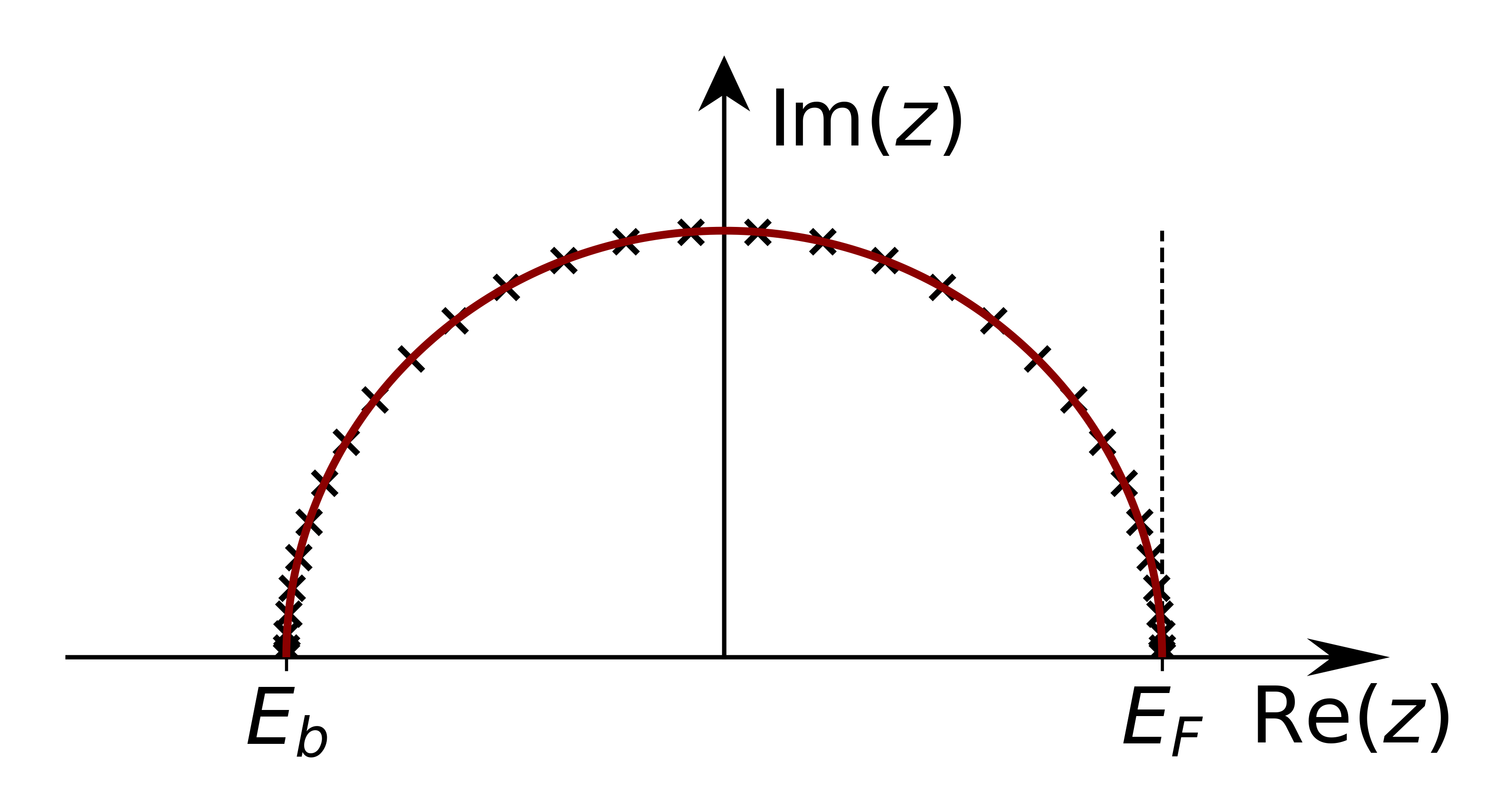
Semicircular contour. The points are chosen according to Gauss quadrature.
Equidistant Contour
<contourDOS n="5400" eb="-1.0" et="0.0" sigma="0.001" l_fermi="T" analytical_cont="T"/>
| Attribute | Description |
|---|---|
| n | Number of energy points in the contour |
| eb | Low energy bound of the contour (specified relative to the fermi energy) |
| et | Upper energy bound of the contour (specified relative to the fermi energy) |
| sigma | Imaginary part for the contour |
| l_fermi | Switch, which determines whether to weight the points according to the Fermi Distribution (if true) or not |
| analytical_cont | Switch, which determines whether to use analytical continuation at the edges of the contour |
| label | Name of the contour (optional) default:"default" |
Defines a equdistant contour between eb and et shifted by sigma into the complex plane.
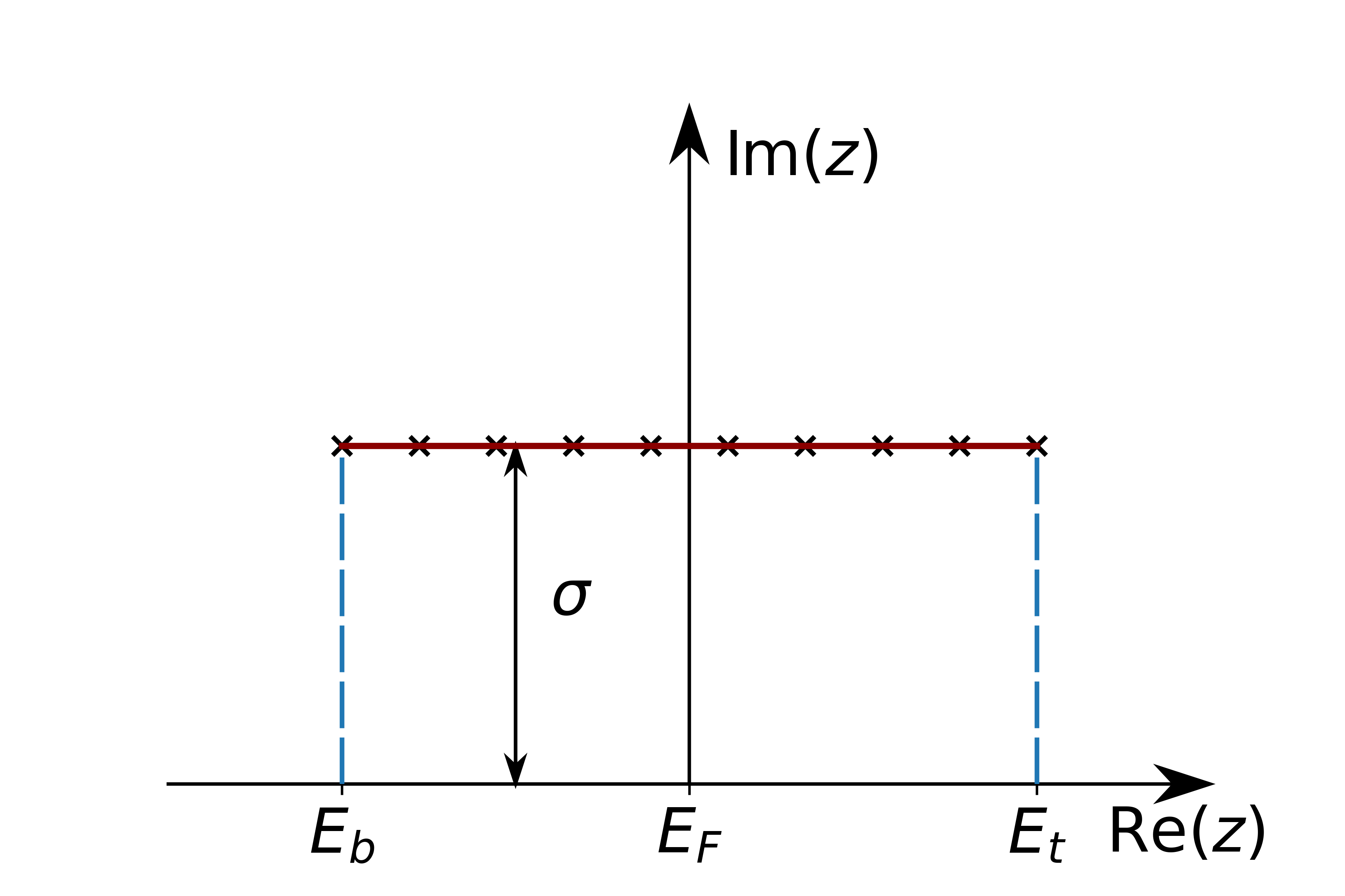
Equidistant contour between eb and et. Lines at the edges symbolize the analytical continuation, which can be performed.
Rectangular Contour
<contourRectangle n1="10" n2="128" n3="30" nmatsub="5" eb="-1.0" sigma="0.005"/>
| Attribute | Description |
|---|---|
| n1 | Number of energy points in the section 1 (see below) |
| n2 | Number of energy points in the section 2 (see below) |
| n3 | Number of energy points in the section 3 (see below) |
| nmatsub | Number of matsubara frequencies considered |
| eb | Low energy bound of the contour (specified relative to the fermi energy) |
| sigma | Defines the inverse temperature to determine the matsubara frequencies |
| label | Name of the contour (optional) default:"default" |
Defines a rectangular contour between eb and the Fermi energy
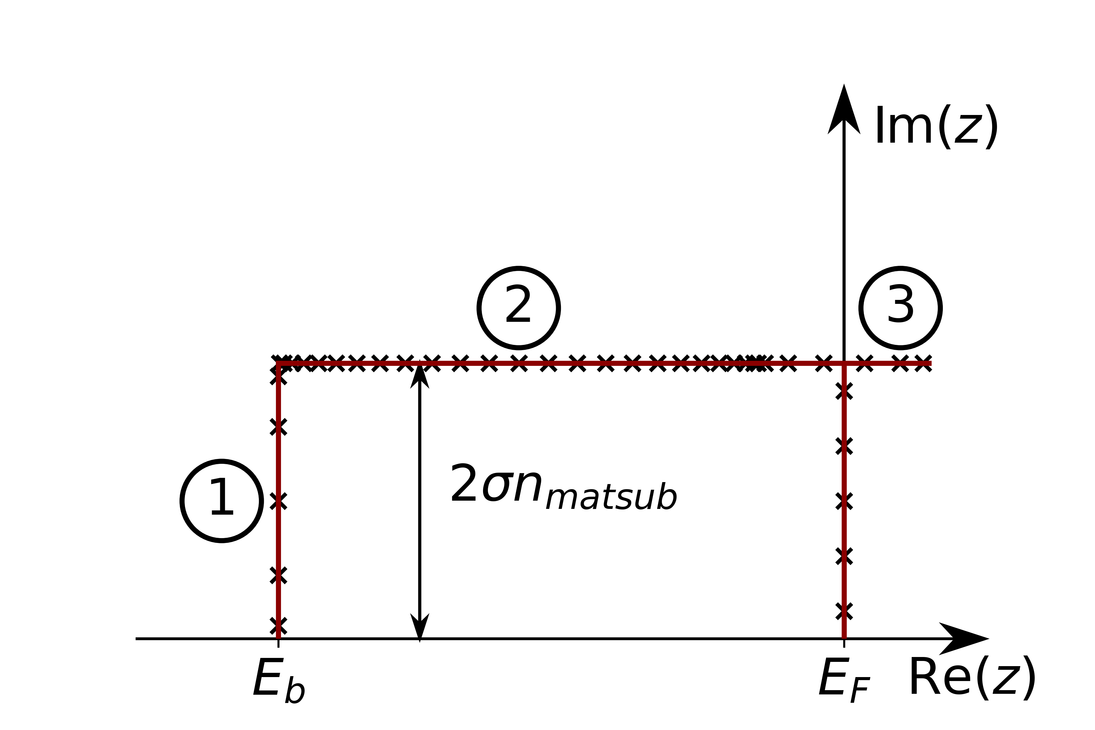
Rectangular contour. Numbers correspond to the number arguments above. The points in all sections are chosen with Gauss quadrature. At the Fermi Energy the matsubara frequencies are also marked
Element Setup
The specification of the Green's Function elements can be provided in another greensfCalculation tag. This element is inserted in the corresponding atomSpecies section behind the energyParameters tag and any ldaU or ldaHIA tags and before the specification of the lo tags.
    <greensfCalculation l_sphavg="T" nshells="0" kkintgrCutoff="calc" label="default">
        <!-- here the actual orbital elements are specified (example,details below)/!-->
        <diagElements s="F" p="F" d="T" f="T"/>
    </greensfCalculation>
| Attribute | Description |
|---|---|
| l_sphavg | This switch determines, whether the Green's Function is calculated with radial dependence (if false) or not |
| nshells | If this optional argument is not zero the intersite elements with the given number of neighbour shells is calculated |
| kkintgrCutoff | This optional argument specifies how the integration cutoff for the Kramers-Kronig-Transformation is calculated. Default is "calc" -> automatic calculation. For more details see below |
| label | Specifies the energy contour used. Has to correspond to a label in the energy contour setup. default: "default" |
If the Green's Functions are supposed to be used for a special calculation, like e.g. the torgue, the format of the element does not change but it is named differently. They may also impose special restrictions on the elements
| Valid Name | Restrictions |
|---|---|
| greensfCalculation | None |
| torgueCalculation | nshells and l_sphavg arguments are not valid. They are enforced to be 0 and F respectively |
Specifying the integration cutoff
For the Kramers-Kronig-Transformation it is crucial to define an upper energy cutoff. This can be controlled via the kkintgrCutoff attribute in the greensfCalculation tag. This allows the following arguments.
| Attribute | Description |
|---|---|
| 'calc' (default) | The integration cutoff is automatically determined from the calculated imaginary part. The cutoff is chosen, so that the integration over the DOS derived from the imaginary part is equal to the number of states in the orbital. This only works for onsite and l-diagonal elements |
| Real Number | Specifies the cutoff fixed relative to the Fermi energy |
| 's', 'p', 'd' or 'f' | Takes the cutoff for the given l-diagonal element (either specified via 'calc' or a fixed cutoff) and uses it for all elements specified in this tag |
Selecting the orbital elements
To specify the orbital elements one of the following two elements has to be added in place of the comment above.
Either the l-diagonal elements can be specified
<diagElements s="F" p="F" d="T" f="T"/>
or a more general definition can be placed here.
    <matrixElements>
        <s> F F F F </s>
        <p> F F F F </p>
        <d> F F T T </d>
        <f> F F T T </f>
    </matrixElements>
The s, p, d and f tags refer to the orbital quantum numbers, which are allowed for the Green's function calculations.